FORWARD
The introduction of extremely low-cost EPROM’s has allowed the introduction of an Auto-ID system used for the automatic calibration of sensors to signal conditioners. The Auto-ID system offers many advantages:
⦁ Calibration can be automatic and fast
⦁ Calibration data is no longer easily lost
⦁ Sensors do not require matched outputs to be interchangeable
⦁ System is low cost
⦁ System is flexible – use is not limited to strain gauge sensors
⦁ Eliminates human errors in calibration
DISCUSSION
An EPROM based circuit is added to the sensor and is programmed with the sensors calibration information. When the sensor is plugged into a compatible instrument, the instrument retrieves the calibration data from the EPROM and calibrates itself to the sensor.
CIRCUIT HARDWARE
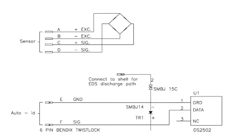
The heart of the Auto-ID circuit is the single wire EPROM chip from Dallas Semiconductor, part #DS2502.
Transient Voltage Suppressors have been added for protection against static electricity. See the schematic in Figure 1.
The EPROM uses only two pins, one for data and the other for the ground reference. The EPROM consists of 128 bytes of programmable storage area and may only be programmed once. Most microcontrollers can communicate with this chip. A programmable, bidirectional, open drain port bit is
required. For timing purposes, it must also be able to switch at sufficient speeds (<1ms). The EPROM’s data line is also an open drain type; therefore, a pull-up resistor is required.
Commands and data are transferred between the devices by momentarily grounding the data line. The data encoding scheme requires that both pins be open drain, since there are times when both devices will be accessing the data line at the same time. For example, to read a bit from the EPROM the microcontroller grounds the data line. While the data line is grounded, the EPROM will respond. It will also ground the data line if the data bit is 0. If the data bit is 1, the EPROM will not ground the data line.
When the microcontroller releases the data line, it will monitor the data line status to see if it remained low or immediately became high. (See the EPROM data sheet for more details on the encoding scheme.) The EPROM manufacturer specifies a range of pull-up resistors. Since there may be a cable between the microcontroller and the EPROM, Auto-ID uses a 2.7K Ohms pull-up resistor. This minimizes the effects of cable capacitance. The pull-up resistor also provides power for the EPROM through the data pin. When both the EPROM and the microcontroller release the data line, the pull-up resistor raises the data line to 5 volts, charging a power supply capacitor inside the EPROM. This charge is sufficient to keep the chip operational during communications.
CALIBRATION
To calibrate an instrument to a strain gauge sensor, Auto-ID must provide the instrument with the data
required to derive a transfer function. The transfer function is a relationship between the input signal (force, torque, etc…) applied to the sensor and the displayed engineering value.
For linear sensors, an instrument requires the following information:
⦁ Capacity (Full Scale)
⦁ Engineering units
⦁ Output at Full Scale
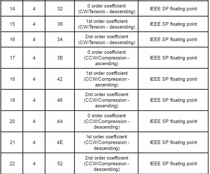
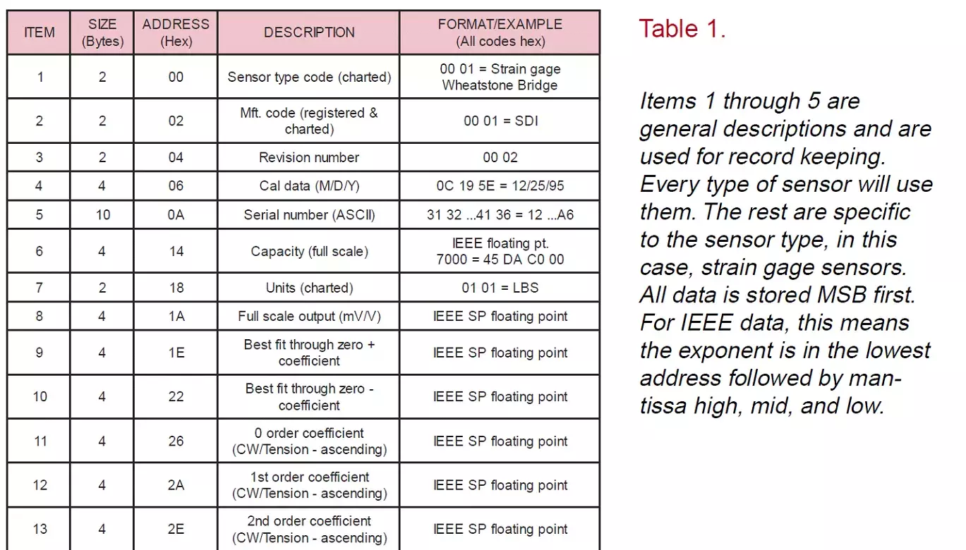
For non-linear sensors, the instrument will require curve fit constants for a more accurate, nonlinear transfer function. See items 11 through 21 of Table 1. The instrument generates the transfer function by
inserting the curve fit constants into the following generic equation: y = Ax2 + Bx + C where y is the force applied to the sensor in engineering units and x is the output from the sensor in mV/V. A is the second order curve fit constant, B the first order and C the zero order.
Subscribe for Insights
Industry insights, trends, events and unmissable content straight to your inbox
Sign up to our newsletter to get insider access to stay up to date with all things custom strain gauge sensing
DATA FORMAT
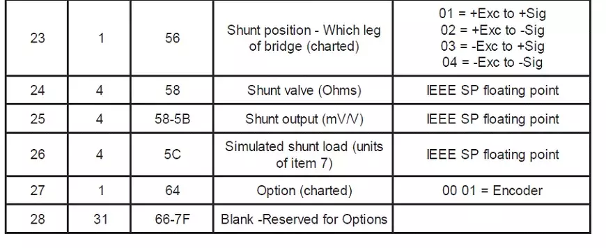
As shown in Table 1, HITEC has defined the memory format for strain gauge Wheatstone Bridge sensors.


Speak to our experts
Provide us with your information and our team will contact you
Rick West
Rick West is the Electronic Design Manager with HITEC Sensors, with expertise in design of instrumentation for strain gage based force and torque sensors. He has a passion for designing/programming electronic devices, electronic communication, and diagnosing field service issues. Rick has 34 years of experience in the field, with specialization in calibration uncertainties, hydraulic servos and residential construction.