All weighing systems are designed so that they exhibit maximum accuracies or resolutions over a defined loading range. Typical resolving power of these systems is 1%, 0.1% or 0.01% of full scale range. For a high accuracy system (i.e. 0.01%), this means that the full-scale capacity of the system is 10,000 times the minimum resolvable weight that the system can measure. For example, if a system is capable of measuring 1 ounce, and is a accuracy system, the full scale capacity will probably be 10,000 oz. (or 625 lbs.). For a low resolution system (i.e. 1%), the full-scale capacity would only be 100 oz. (or 6.25 lbs.).
It’s interesting to note that both a 1% system and a 0.01% system are capable of measuring a given weight to the same degree of accuracy and resolution. The real advantage of the higher accuracy (and much more costly) system is the range over which it will make measurements to this accuracy.
Most electronic weighing systems utilizing load cells as the sensing element have two things in common: they have a structural element that acts like a spring which deforms when a force (or weight) is applied and some form of sensing device that is capable of measuring this deformation. The resolution of these systems is governed by how much deformation the structural element can tolerate and the sensitivity of the sensing device used.
In all of these systems, the structural element is designed to be compatible with the sensing element used and normally is designed to have the maximum possible deformation when the anticipated full-scale load is applied. The sensing element is the primary part of the system that determines the obtainable resolution or accuracy of the system. The problems associated with overload are invariably connected to the structural element of the system.
Keeping in mind that the structural element of the load cell deforms as we apply weight, we can define four distinct regions of operation for the typical weighing system: The Normal Operating Range – The structural element deforms proportionally and repeatability to the applied weight and can considered to be perfectly elastic.
The Moderate or Allowable Overload Range – The structure still can be considered elastic, but the deformation may not be exactly proportional to the applied load. No detectable damage will occur to the system from occasional operation in this region. This region can be further divided into two sub-regions: the “Stated” and the “Actual” allowable overload range. The reason for this is that the upper border of this region is difficult to predict with accuracy and therefore manufacturers apply a “factor of safety” and derate (hopefully) their stated range. The amount that different manufacturers “derate” varies tremendously even among similar products. the factors that enter into the derating are those of material property variations, unknown loading conditions, potential risk costs, and unfortunately….sales appeal.
The Severe Overload Range – Here the structure starts to exhibit signs of permanent damage. After removal of the overload, the structure might not respond repeatedly to any applied load. Minor excursions into this region are difficult to detect, but normally are associated with unexplained changes in calibration or “zero shifts”. Loads applied in the upper part of this region usually show signs of physical damage. It is sometimes helpful to get the manufacturer’s estimate of the upper border of this region, especially if structural failure cannot be tolerated.
The Destructive Overload Range – The structure FAILS. The primary consideration here, is HOW it fails. Compression failure is usually considered “fail-safe” with the load being automatically transferred to the support structure of the weighing system. Precautions should be taken, however, to protect against outwardly thrown shrapnel. Tensile failure allows any suspended weight to fail, possibly with damaging effects. Needless to say, this is a region that one never hopes to be in.
Of these four regions, it is obvious that we never wish to exceed the allowable overload range. In order to protect the structural element in an electronic weighing system, steps must be taken to ensure that the element is never loaded beyond its allowable overload range. If the anticipated maximum overload falls within this region, there’s no problem. However, if there’s any possibility that a damaging overload can be applied to a system, Murphy’s Law will ensure that it will be. Therefore, some added protection for the weighting system will be required.
The most straight-forward method of overload protection is simple derating of the system’s “Normal Operating Range.” For example: assume that a 100 lb. scale on a production line is used to weigh components with an accuracy of 1/10 of a pound (i.e. 1.0% accuracy). If the stated allowable overload capacity of the system is 150% of full scale (i.e. 150 pounds), you can be confident that a 200 pound operator will use that scale as a seat every lunch hour. If the manufacturer has applied a sufficient safety factor to his stated overload range, the scale might survive as long as the operator sat down gently. If, however, a 200 pound scale with the same allowable overload factor was installed, the operator could eat his lunch and have a 100 pound person join him without damaging the scale. If the scale still had to weigh components with an accuracy of 1/10 of a pound, however, the 200 pound scale would require twice the accuracy of the original (i.e. the new scale would require an accuracy of 0.05%).
The next method of overload protection is the “Mechanical Stop” system. Since the structure of a weighing system deforms as weight is applied, a mechanical stop could be installed that would be contacted at a given force, thereby preventing further force being carried by the structural element of the scale. Figure 1 shows a simple spring scale with this type of protection.
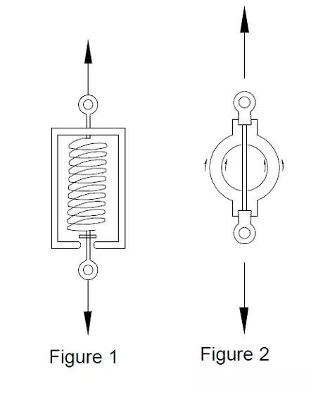
Although a spring scale was shown, this type of overload protection is often applied to “stiff” structural elements as are found in load cells. Assume that a load cell deflects .005” at its rated capacity and has an allowable overload factor of 150%. This would indicate that the load cell could deflect .0075” before being damaged. Therefore, if we could arrange a mechanical stop that would engage when the applied load caused the load cell to deflect between .005” and .0075”, we could protect the load cell from damaging overloads. Figure 2 shows this type of overload system designed around a common “proving ring” structure as is often found in low capacity load cell designs. Although simple in concept, “mechanical stop” overload systems are often quite difficult to implement in weighing systems that have very stiff structural elements. In the above example, the gap that is required must be machined (or set) with great accuracy. If the gap was less than .005”, the mechanical stop would be engaged before the full scale capacity of the scale was achieved, thereby, giving erroneous readings at high loads.
On the other hand, if the gap was just slightly greater than .0075”, the structure would be loaded into a region possibly causing permanent damage before the mechanical stop was engaged. Even if the mechanical stop system was machined correctly, a dirt particle that has just the right size will manage to lodge itself in the carefully designed gap and lead to premature gap engagement (Murphy’s Law).
The normal method of designing an effective mechanical stop system is to first design the structural element to have the largest possible deflection that is consistent with the sensing technique used. This might even involve adding a high deflection spring in series with the load cell just to give added deflection to the system. Figure 3 shows this type of system.
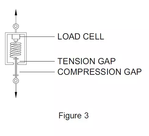
The other design criterion for this type of system is to protect the system from dirt particles either by protective covers or arranging for physical inspection and periodic cleaning of the gaps.
If the weighing system is designed for high speed operation, the technique of softening the structure in order to make the mechanical stop system effective cannot be used. High speed systems dictate greater stiffness, not lower ones, and therefore, the mechanical stop system is extremely difficult to apply with success. We’ll examine “preloaded spring” overload systems as a modified mechanical stop system which effectively gets us around this problem.
We previously explored the possible use of a “soft” spring in series with a “stiff” load cell in order to achieve enough deflection to enable a mechanical overload stop to function efficiently. We also determined that the addition of the spring lowered the natural frequency of the system and, therefore, also reduced the speed of the weighing system. For systems that required high response rates, the series spring approach for overload protection is impractical…unless we could somehow make the spring “stiff” also, until an overload occurred. The “preloaded” spring system does precisely that.
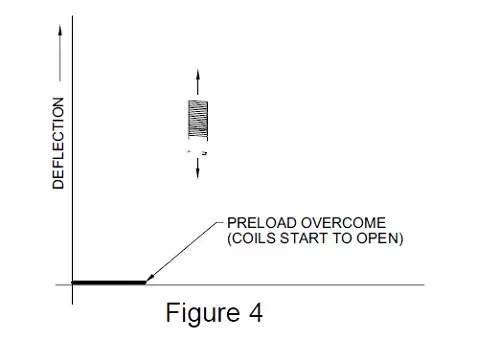
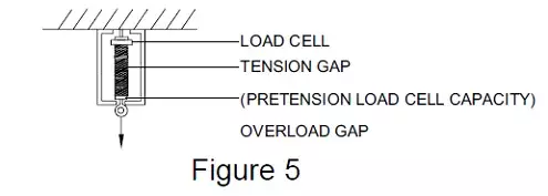
The simplest form of a preloaded spring is a simple tension spring that has been wound with a controlled pretension. Figure 4 (above) shows a plot of the deflection versus applied force for this type of spring. For low capacity tension load cells (i.e. below about 100 lbs.), this type of spring can be readily added to the load cell and provides tensile and side load protection for the load cell. A sketch of this system is shown in Figure 5 (below).
Subscribe for Insights
Industry insights, trends, events and unmissable content straight to your inbox
Sign up to our newsletter to get insider access to stay up to date with all things custom strain gauge sensing
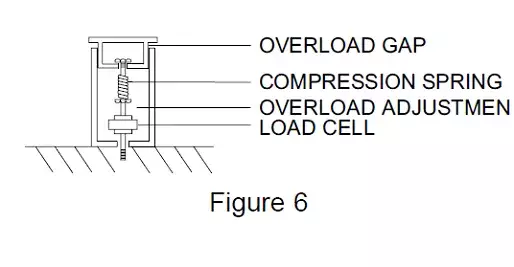
A compression spring can also be preloaded, but unlike the tension spring, requires some additional hardware to accomplish the task. Figure 6 shows a simple compression spring overload system, where the preload is set by an internal nut.
One directional overload system using preloaded springs are rather easy to envision and implement. Two directional systems are more complex, but are still quite practical. With all of the advantages of the preloaded spring overload systems, how come more of them aren’t used?
Quite frankly, I don’t know. Maybe because load cell manufacturers don’t have to replace an obviously overloaded load cell under warranty. Seriously, there are some drawbacks to the preloaded spring systems. They tend to be limited to the smaller capacity systems (under 10,000 lbs.), they add some mechanical complexity to the weighing system, and they also can have strange effects on systems that are sensitive to relative deflections of components.
An example of the last problem would be found in “steelyard” conversions using load cells. If in the conversion, a preloaded spring overload protection system was also incorporated, every time that the overload system was activated, it would “reset” itself to a possibly different overall assembly length.
This would result in an apparent “zero shift” in the load cell. The key point is that load cell applications such as the steelyard conversion also requires that the installed length of the system be constant or else differing tare weights will be suspended on the loadcell. In the preload spring system, reset tolerances can be on the order of plus/minus .020 due to hysteresis losses between coils of the spring or “seating problems of the various components. The test of the relative suitability of a preloaded spring system would be to determine the effect of adding a variable andpossibly non-reatable length load cell to the system.
For weighing systems that can tolerate physical separation of the load cell link, a simple shear pin system might be a low-cost method of protecting a high price load cell. Thomas Register lists over a dozen suppliers under the category of Pins, Shear. All of our discussion of overload up until now as dealt with those loads that have been relatively slowly applied.
Have you ever seen the act where a man places a massive stone block on his stomach and then has an accomplice break it in half with a sledge hammer? Or have you ever tried to drive a nail through a thin sheet of plywood that didn’t have any support behind it? If so, you have either witnessed or observed at first hand, the control or miss-control of shock loading.
Shock loading is a significant factor in determining whether or not a weighing system will survive in the environment in which it’s placed. The very feature that makes electronic weighing systems so attractive (their high operating speed) makes them especially prone to damage from shock loading. In order to better understand the effects of shock loading, let’s examine a fictional case of shock load damage on a 50-pound scale.
A ten-pound box of nails is accidentally dropped from a height of 10 inches on a 50 pound (full scale) counting scale. After the incident, the scale has experienced a shift in zero reading that can no longer be nulled out. In order to determine what happened, let’s slow the action down and repeat the accident. As the box of nails is dropped, it begins to accelerate gathering momentum. One quarter of a second later, moving now at 5 miles per hour, it contacts the top surface of the scale. Since the scale is very stiff, the box of nails must now come to zero velocity in a very short distance (typically .005”). This means that the mass must undergo tremendous deceleration, which is on the order of 160 times the acceleration due to gravity. The forces generated by this acceleration (or deceleration), could build to 1600 pounds if nothing happened to relieve the force. However, the cardboard container starts to crush and many of the nails inside the container start to shift, which absorbs some of the energy of the fall. Since the box starts to crush, the effective distance over which the weight is accelerated also increases, which further reduces the acceleration forces. While all of this is occurring, the upper surface of the scale, which has a certain amount of mass, produces a resisting force, which is directly proportional to the amount of mass it contains, thereby tending to protect the load cell that is mounted directly below. However, the mass of this platform has been purposely minimized in order to reduce the tare load on the load cell and enhance its high-speed performance. This is one reason why large truck scales with their huge platform masses are not too susceptible to shock loads; the mass of the platform tends to absorb them. The shock load force is now attenuated by the container crushing, the nails shifting, and the resisting force of the upper platform to the load cell. The two surfaces held together by the bolts in this connection are stable because of the friction that exists between them. In the original process of tightening, these surfaces were preloaded in some manner and the surfaces deformed, which was then maintained by the frictional forces. The shock load force entering the bolted connection can now serve to change the original amount of energy stored in the connection.
If the load cell is properly designed, the conditions of bolting should have only minor effects on the operating zero point of the load cell. However, because of space limitations, the load cell was designed in such a manner so as to utilize the structural stiffness of the attached members, which is all right provided the attached members remain attached in the same manner at all times. Although hard to visualize, joint shifting is a prime cause of unexplainable zero shifting in a scale system that is subjected to shock loading conditions. After having passed the bolted connections, the force now enters the highly stressed member of the load cell that is used to measure the load. If the force has not been sufficiently attenuated by this time, the stresses may be high enough to yield or break the load cell. If the load cell does yield, further deflection is added to the system, which in turn serves to reduce the acceleration forces.
After passing the load cell, the force again passes through another bolted connection, causing the same problems as were previously mentioned, and arrives at the base structure of the scale. If the base is massive, it reacts to the applied force by resisting acceleration, or if light weight tends to pass the shock force on through the rubber mounting feet, further tend to attenuate the shock wave to the point that the table upon which the scale is placed, carries little more than the additional 10 lb. load that would exist if the nails had been applied normally to the scale. In fact, many times, the scale can be assumed to be the protection device for the table upon which it sets.
From this fictional story of a shock loading incident, some real insights should be evident. If we can somehow increase the distances over which the suddenly applied load is stopped, the forces produced by this deceleration are greatly reduced. The bumpers on the newer model cars are prime examples of this design concept. Another possibility for minimizing the effects of shock loading is in the careful management of the internal masses of the scale itself. For example, a preloaded spring overload system can be effective for shock loads as long as the load cell does not have to contend with large inertia loads.
The proper use of elastomer mounts also can be an effective method of controlling shock loads again by adding to the effective distance over which the load is decelerated and also by converting some of the energy to heat in the elastomer itself.
Earlier we dropped things on scales and attempted to slow down the action so we could visualize how the force was channeled through the structure, with the shock or impulse being absorbed or modified by means of either the relative masses of the scale’s components or generated as heat in elastomer (rubber like) elements. It turns out that for effective control over shock loads, the scale designer must pay attention to the masses of the various components of the scale and their relative positions in the force path of the scale. Two types of spring preload overload protection systems are shown in Figure 7 (below).
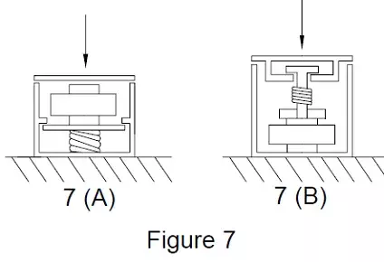
While both of the designs shown will protect against normally applied overloads, the system shown in Figure 7 (B) will also offer relatively good protection for shock loads, while 7 (A) will not. The reason is that a shock force applied to the input platform is reacted by the acceleration forces produced by the upper platform, the housing of the load cell, and the lower platform which is spring loaded against internal “stops” in the housing of the overload protector. In this system, only the inertial force of the upper platform helps absorb some of the shock load, while the inertia forces generated by the load cell housing and the lower platform serve only to prevent the applied shock load from reaching the spring, which is supposed to collapse and protect the load cell. Since the inertia of the load cell housing and lower platform react to the applied shock load, the force which is the very thing that the overload protector was supposed to protect in the first place.
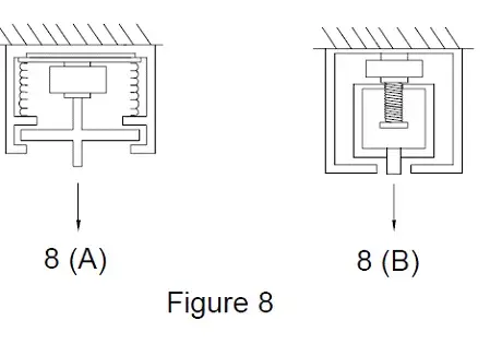
The design in Figure 7 (B) on the other hand was basically only one moving part under shock loading conditions…the upper platform, whose inertia tends to react to the applied force in a helpful manner to begin with. Figure 8 shows two analogous overload protectors for tensile shock load protection. Again, Figure 8 (A) is poor for shock loads and Figure 8 (B) is all right.
There are virtually unlimited ways to design efficient spring pre-load overload systems, working in either tension, compression, or both. The one inherent feature in all designs with regard to their suitability to shock loading can be recognized by examining the location of the overload system with respect to the housing of the load cell. In general, shock protection is only afforded by those designs where the base of the load cell is directly connected to the frame of the machine or in some way is prevented from accelerating and producing damaging reaction forces. Shock loads normally don’t stop having damaging effects after simply being channeled through overload stops. Consideration should also be given to the shock produced as a load is suddenly removed from a scale. In these cases, the mass of the upper platform which helped in the normal overload situation, suddenly becomes a moving mass which can apply damaging forces to a load cell if not considered.
To guard against this condition, the best approach would seem to be to keep the upper platform as light as possible, to reduce the return force (after an overload has been removed), Prevention of the shock load from damaging the surfaces of the overload gaps themselves, or attenuating the shock load as it by-passes the load cell is probably best handled by the judicious use of elastomer elements, either in the overload gaps themselves, or somewhere else in series with the by-pass force path.
Speak to our experts
Provide us with your information and our team will contact you

Domenic El-Achkar
Domenic El-Achkar is Director of Engineering for HITEC Sensors. He started with the company in May of 2000, as a Co-Op student while earning his B.S. in Mechanical Engineering at UMass Lowell and later earning his MBA. Domenic has developed his engineering capabilities from applications support through design, test and measurement, management, and departmental leadership. Domenic combines broad technical knowledge with a commercial mindset and good communication skills to be a very effective customer-facing technical leader. He enjoys visiting customers, developing partnerships, innovative sensor designs, and helping customers solve problems.