I. DEFINITION AND PROBLEM ANALYSIS
While difficult to exactly define, the concept of force is easily comprehended. The attraction between two bodies is a gravitational force, which has been given the unique designation as WEIGHT. Forces can also be produced by the deflection of spring elements, hydraulic pressure acting on pistons, magnetic attraction and repulsion in motors and inertial effects generated by the acceleration of mass.
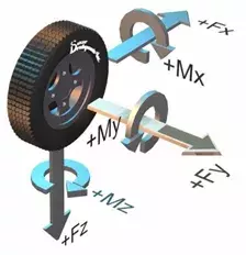
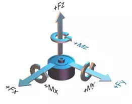
The analysis of the effects of force is most easily accomplished by treating forces as vector quantities. As a vector, the force has a defined direction, line of action and point of application. Two or more forces acting in concert can be analyzed by summing the force vectors to produce an equivalent single force.
Conversely, a single force can be thought of as consisting of the vector sum of several forces acting in an arbitrarily defined coordinate system. Analysis is greatly simplified by choosing a rectangular coordinate system. In such a system, the effects of each of the force COMPONENTS can be analyzed independently and later combined if required.
The analysis and measurement of forces is best handled by the vector techniques mentioned above and the use of NEWTON’S laws which basically conclude that a body which is not accelerating cannot have an unbalance of forces acting upon it (i.e.: The vector sum of all forces acting on a non-accelerating body must equal zero). The most used technique utilizing vectors and this basic concept is the FREE BODY DIAGRAM. Review of this technique in any basic physics, static’s or dynamics text book is recommended for successful analysis and measurement of force.

II. TRANSDUCER PRINCIPLES
Virtually all force measurement transducers utilize a spring-like structure, which deforms under the application of a force and a sensor to detect this deflection. The spring in the strain gauge transducer is referred to as its STRUCTURE and deflections of the structure sensed by intimately boned electrical conductors whose resistance changes with deformation (STRAIN GAUGES).
The total deflection of a strain gauge transducer is extremely small (less than 0.015” and typically 0.003”) when forces are applied at the full-scale capacity of the transducer. The deflections may be considered linear and smaller forces produce smaller deflections.
Even though the deflections are small, occasional measurement problems occur due to this deflection.
Dynamic forces such as those produced by impacts or energy releases are particularly difficult to measure because of band width requirements. The transducer, because of its spring-like characteristics,
can both amplify certain frequency components of the measured force and/ or affect the actual forces in the system into which its installed. Forces generated in STIFF systems such as bolted connections
can be seriously affected by the stiffness of the transducer and special care must be taken to ensure valid measurement.
The structures used for strain gauge transducers generally consist of beams, diaphragms, shear beams or columns with the choice of structure dictated by force magnitudes and geometric size constraints. The strain gauges are normally applied in multiples of 4 and wired into a WHEATSTONE BRIDGE configuration which allows measurement of the CHANGE in resistance of the gauges resulting from the force related deformation of the structure.
The Wheatstone bridge produces a variable voltage output proportional to the applied force when excited by a fixed voltage source. Typical outputs of a strain gauge transducer are on the order of 2 millivolts per volt of excitation when the transducer is loaded to full scale with correspondingly smaller voltages generated with lesser forces. Because of this small signal level, amplification is normally required. Transducer indicators normally supply both the excitation voltage and the amplification required for the transducer and therefore is more expensive than simple voltmeters.

Subscribe for Insights
Industry insights, trends, events and unmissable content straight to your inbox
Sign up to our newsletter to get insider access to stay up to date with all things custom strain gauge sensing
III. SELECTION OF FORCE SENSORS
The measurement of force can be performed directly be installing the transducer in SERIES with the force path to be measured. Indirect force measurement can also be performed by the measurement of a portion of a portion of a multiple path system or reaction forces where the primary force path is inaccessible.
A well-designed transducer can be considered to be a force vector resolver and the signal obtained should be proportional to those force components which lie on, or parallel to, the FORCE SENSITIVE AXIS of the transducer. The transducer might have to support off-axis force components but should not respond to these forces. Because of this, structural considerations limit the transducer with regard to not only the maximum measured load, but also the maximum extraneous (off-axis) forces that may be applied. Therefore, specification of a transducer requires the estimation of the maximum anticipated loads, which will be both, measured and supported by the transducer.
From this estimation, the resolution of the transducer can be estimated by noting that typical strain gauge transducers (coupled with modern transducer indicators) can resolve approximately 1 part in 1000. The resolution of the force measurement system is therefore 1/1000 of the rated capacity of the transducer. Other factors affecting the accuracy of force measurement are largely environmental such as ambient temperature and pressure.
Temperature effects are compensated for in the transducer and are normally held to levels of .002%F.S./F as an effect on zero load signal (temperature produced zero offset shift) and .002%Rdg/F for sensitivity (span) change. Ambient pressure effects are minimal in OPEN construction transducers or can be minimized in PRESSURE BALANCED transducers.
SELECTION OF A TRANSDUCER CAN BE SUMMARIZED AS FOLLOWS:
1) Analyze the force to be measured and determine:
A) Its maximum value.
B) Its dynamics (are high response frequencies required?).
C) The effects of interposing a stiff spring (the transducer) in the force path.
D) The maximum extraneous loads to be supported but not measured by the transducer.
2) Analyze the system in which forces are to be made.
A) Can the sensor be installed in the primary force path or is indirect measurement indicated.
B) What are the physical size restrictions and what mounting configuration is required.
3) Determine if the inherent resolution of 1 part in 1000 is adequate for the measurement.
4) Determine if environmental effects, such as temperature and pressure, will cause serious
degradation of the measurement.
5) Choose a transducer indicator or signal conditioning system which is compatible with the transducer
and has response characteristics compatible with the object of the measurement. With these points
in mind, selection of a force sensor is generally straight forward and successful.
HITEC Sensor Developments has had considerable experience in the design of force measurement systems and would be glad to assist in any of the above analysis or selection areas.
Speak to our experts
Provide us with your information and our team will contact you

Domenic El-Achkar
Domenic El-Achkar is Director of Engineering for HITEC Sensors. He started with the company in May of 2000, as a Co-Op student while earning his B.S. in Mechanical Engineering at UMass Lowell and later earning his MBA. Domenic has developed his engineering capabilities from applications support through design, test and measurement, management, and departmental leadership. Domenic combines broad technical knowledge with a commercial mindset and good communication skills to be a very effective customer-facing technical leader. He enjoys visiting customers, developing partnerships, innovative sensor designs, and helping customers solve problems.