For most force measurement applications, the strain gauge based transducer can be relied upon to faithfully convert a mechanical input into a proportional electrical analog output signal. However, when the mechanical input is either applied or changes at a rapid rate, the sensor may distort the conversion and the user should be aware of the possible consequences of this distortion. This article will explore the sources of these distortions, the possible problems created, and the normally applied corrections.
A force sensor (which also includes torque sensors), consists of a structure which deforms upon the application of force and a system which senses this deformation, producing a proportional output signal. While these articles concentrate on strain gauge based sensors, it should be noted that the above definitions are extremely broad and define many other force sensing systems as well. A spring is also a structure which deforms under an applied load, and the structures of transducers may be considered as stiff springs for analysis purposes. When a mass is connected to one end of a spring, and the mass is deflected and then released suddenly, the mass will be observed to oscillate and eventually return to its undisturbed position. The frequency at which the mass will oscillate is determined by the magnitude of the mass and the stiffness (or spring constant) of the spring. The equation which describes this NATURAL
FREQUENCY is given below:
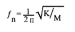
Where K is the spring constant in lbs/inch and M is the mass of the body in lbs/in/sec2. On earth, we often relate the mass of a body to its weight and M may be replaced by the weight of the object in lbs. divided by the acceleration due to gravity of 386 in/sec2.
If the spring was perfect and there were no frictional losses as the body passed through our atmosphere, the system would not halt, but would continue to oscillate forever. The fact that the oscillations do eventually stop shows that there is some form of retarding action which in a spring mass system is referred to as DAMPING. The existence of damping does affect the natural frequency, lowering it somewhat, but for the small amount of damping normally found in force sensors the above equation is still accurate enough for most purposes. Since the natural frequency of a spring-mass system depends upon not only the stiffness of the structural element but also upon the mass, the natural frequency of a force sensor is not constant, but varies over a certain range of possible natural frequencies. When a force sensor is unloaded, its structure still supports a small mass consisting of its input mounting structure and some of the mass of the spring element itself. If this unloaded transducer is lightly struck, it will oscillate at its highest possible natural frequency often referred to as its RINGING FREQUENCY. Ringing frequencies typically range from 50 Hz for low capacity sensors to 10 KHz for high capacity sensors. On the other hand, when these same sensors are deadweight loaded up to their rated force capacities, their natural frequencies drop because of the increased mass term in the equation. In this condition, it will be found that all force sensors, regardless of capacity, will have about the same natural frequency. For strain gauge based sensors, this loaded natural frequency will always be approximately 60 Hz. For lesser mass loads, the natural resonant frequency will be higher than 60 Hz but always less than the unloaded ringing frequency. The importance of these natural resonant frequencies will become clear later on.
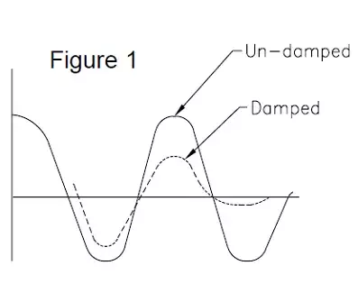
Another way of considering the oscillation characteristics of a force sensor, is to consider it as an energy converter. For example, an electronic scale normally contains a strain gauge based sensor and when an object is placed upon the platform, the platform starts to accelerate toward a new equilibrium position. When the platform reaches this position, however, it now has gained energy in the form of momentum and the platform continues past its equilibrium point. Now, the spring element of the sensor starts applying more and more restraining force, causing the platform to stop its motion and start returning to the equilibrium point. But again, on its return trip, the platform gains momentum and again passes by. If no damping is present in the system, the platform would never come to rest but instead would continue to oscillate about the static equilibrium point. The method used to account for this phenomena in electronic scales is to either add some form of damping and/ or recognize that the oscillations occur equally about the equilibrium point and use some form of electronic signal conditioning to extract the correct weight reading from the scale. Figure 1 below shows the expected motion of both a damped and an undamped system.
The response of a force transducer to a varying force input can best be explained by an example:
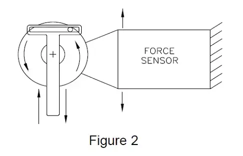
Figure 2 shows a simplified mechanism used to convert rotary to reciprocating motion. The mechanism is commonly found in hand tools such as saber saws and reciprocating sanders. The bearings in such a mechanism are subjected to radial forces that are sinusoidal in nature and occur at the rotational frequency of the drive motor. From physics, the dynamic force produced is relatively easy to predict, being proportional to the mass of the reciprocating part, its maximum displacement and the square of the angular velocity of the drive motor.
One method of measuring this oscillating force would be to mount the tool on a force sensor with the reciprocating axis aligned with the force sensitive axis of the sensor and then turn on the motor. If we examine the output signal of the transducer and compare its peak value to the predicted value at various motor speeds, as shown plotted in Figure 3, we would find that they do not agree. At low speeds, the values closely agree but the force transducer always indicates a higher force than is predicted.
As the rotational speed increases, we find that the error also increases and eventually reaches a maximum value. The point at which this maximum error occurs will coincide with the Natural Frequency of the transducer measured with the mass of the supported tool assembly.
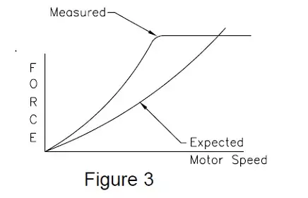
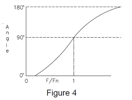
As the rotational speed is further increased, we note that the error starts to diminish until the predicted value and the measured value again agree. This point will also be found to be dependent upon the Natural Frequency of the system, occurring at 1,414 times the natural frequency. Unfortunately, these three rotational velocities 0, Fn and 1.414Fn), are the only velocities where we can be certain about the data obtained from a force sensor. And, even worse, the data obtained is only known to be correct as far as magnitude at 0 and 1.414Fn. If we closely examine the direction of the force input and compare it with the direction of the output signal from the sensor, we would see that they agree in direction only at values close to 0 RPM. In fact, at speeds above the natural frequency, the sensor signal indicates a reversed signal, which is often interpreted as a wiring error rather than an acknowledgement of a misunderstood physical phenomena. If this PHASE information relating the time/direction information is plotted, we can better see the relationship between the input force and the output signal typically produced by a force sensor. This is shown in Figure 4.
At this point, it is tempting to simply “give up” the measurement and relegate all force sensors to the local super-market where they can accurately weigh non-moving objects such as meat or apples. If, however, we can accept some small errors, we can still measure dynamic forces.
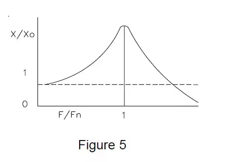
Figure 5 shows the correction factor which can be applied to a typical strain gage based transducer to correct its output signal at various frequencies expressed in relation to the sensor’s natural frequency. The curve is identical to that found in all textbooks of mechanical vibration and is known as the transmissibility of a spring/mass system. The shape of the curve and the magnitude of the error will also be found to be dependent upon the amount of DAMPING present in the system which is generally unknown but can normally be estimated as having a DAMPING FACTOR of less than 0.1.
The equation which describes this curve (in BASIC notation) is:

Where X/Xo is the magnification factor created by the sensor at frequency F related to its natural frequency Fn with a damping factor d. The phase relationship, plotted in Figure 4, can be described with the following equation:

Subscribe for Insights
Industry insights, trends, events and unmissable content straight to your inbox
Sign up to our newsletter to get insider access to stay up to date with all things custom strain gauge sensing
Where angle is in radians and TAN -1 is the arc tangent function. These equations show that force input frequencies up to 1/10 the natural frequency of the sensor will produce errors of less than 1%. Force inputs of 1/4 the natural frequency produce errors of 10% and a 30% error can be expected at forcing frequencies equal to 1/2 the natural frequency.
With this in mind, the general solution to choosing a force transducer for a dynamic force measurement is to choose one that, when installed, has a natural frequency at least 10 times that of the highest frequency to be measured. In this way, measurement errors can always be assumed to be less than 1% which is generally accurate enough for most engineering purposes. This value of 1/10 the natural frequency can be considered as a good “rule of thumb”.
Normally, a force sensor is chosen by selecting a full scale capacity slightly above the highest force level anticipated for the measurement. In this way, maximum signal levels and maximum resolutions are obtained. However, for dynamic force measurements, it should now be apparent that the spring constant of the sensor is an equally important consideration.
Since higher spring constants are normally associated with higher capacity sensors, oftentimes it is necessary to lose some resolution to gain higher natural frequencies. The above example and discussion is related to the effects of a forcing function of a single frequency. A common application for sensors is that of determining the magnitude of forces acting in various structures.
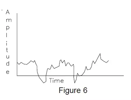
For example, it might be desirable to know the forces acting upon the engine mount of an automobile as it is driven over various road surfaces. If such a sensor is fabricated, installed, and its output recorded, the resulting signal might appear as shown in Figure 6. How accurately does this signal correspond to the actual force input to the sensor? The sensor will distort the signal by various degrees depending upon the ratio of the force input frequency to that of the natural frequency of the sensor.
Therefore, if we know the frequency of the input force, we could correct the output data. But looking at the recorded signal…what frequency do we use? Over a century ago, a French mathematician by the name of Jean-Baptiste Fourier determined that any time varying phenomenon could be described by a series of sine waves at various frequencies and amplitudes, which when added together would duplicate the original phenomenon. Because of the equivalence, it is possible to convert a typical sensor signal recorded in the time domain such as shown in Figure 6.
How accurately does this signal correspond to the actual force input to the sensor? The sensor will distort the signal by various degrees depending upon the ratio of the force input frequency to that of the natural frequency of the sensor. Therefore, if we know the frequency of the input force, we could correct the output data. But looking at the recorded signal…what frequency do we use?
Over a century ago, a French mathematician by the name of Jean- Baptiste Fourier determined that any time varying phenomenon could be described by a series of sine waves at various frequencies and amplitudes, which when added together would duplicate the original phenomenon.
Because of the equivalence, it is possible to convert a typical sensor signal recorded in the time domain such as shown in Figure 6 to a frequency domain representative as shown in Figure 7. This type of signal transformation is commonly referred to as a Fourier Transformation. Another way of viewing this transformation process is to consider a method in which the frequency domain plot may be determined directly from the sensor output.
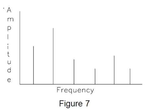
Figure 8 shows a series of electronic notch filters which are set up at various pass frequencies.
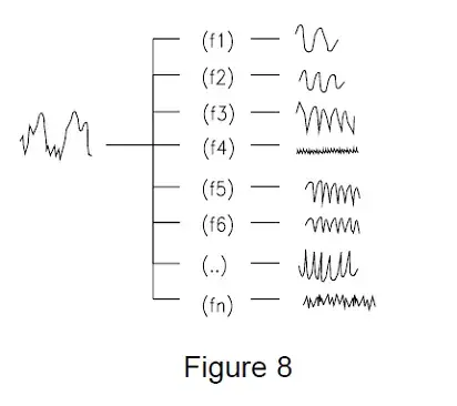
A signal entering the input to this series of filters will be separated into components of different frequencies, much like sand being sifted through meshes of different sizes. If we add these individual frequencies back together again (perhaps using a summing amplifier), we could reconstruct the original signal. Since sensor inaccuracies are related to input frequencies, the frequency domain representation of the output is very helpful. For example, Figure 9 (below) again shows the recorded signal as previously shown in Figure 7, along with the sensor’s frequency related correction curve.
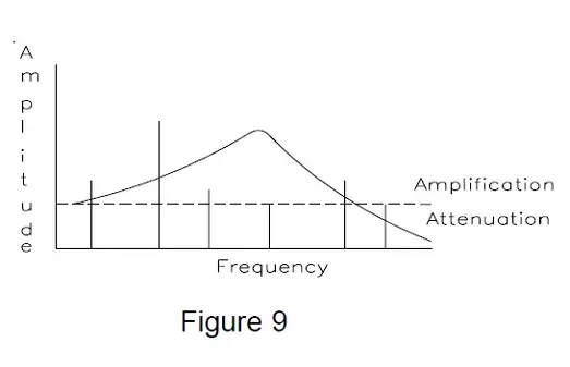
Examining the amplitude of each frequency in turn, we can determine the amount that the sensor amplified (or attenuated) each individual component and construct a new frequency domain curve representing what the input signal must have been like to produce the recorded sensor output. This corrected frequency domain plot is shown in Figure 10.

We can even go further, if necessary, and construct a time domain plot from the frequency domain plot to see what the actual force input had to look like. The above discussion serves only to produce a good mental picture of how to analyze frequency related sensor distortions.
As a practical matter, keeping sensor/mass natural frequencies high relative to the forcing frequencies eliminates most correction requirements. Another technique used is to simply eliminate high frequency signal components which may be distorted by using low pass electronic filtering. Most signal conditioning systems already contain this type of filtering and the user should be cautioned to check to ensure electronic response characteristics compatible with the measurement objectives.
Elimination of high frequency components is not generally damaging to most measurement situations. For example, if sensor output data is simply displayed on a digital or analog display for real-time interpretation by an operator, frequencies above approximately 4 Hz will do nothing more than blur the display and, therefore, should be eliminated in the first place. Recording typically roll off at frequencies below 100 Hz for mechanical pen writers and slightly higher for light beam recorders. Very high-speed tape systems might get to 1000 Hz and direct computer analog to digital converters run anywhere from 1 Hz to 100 KHz sampling data and assume the signal samples (Aliasing errors). Also, when mechanical components are involved, they possess mass and in themselves tend to restrict rapid force changes.
Virtually everything you ever want to know about a mechanical system occurs at frequencies below 100 Hz, with probably +90% of the action occurring below 30 Hz. As a final note, instrumentation systems (spectrum analyzers) are available which accept time domain signals and convert them into frequency domain plots in real time (i.e., as they occur). These instruments perform the same function as the filter sieve and present measurement data in a different format for analysis.
Speak to our experts
Provide us with your information and our team will contact you

Domenic El-Achkar
Domenic El-Achkar is Director of Engineering for HITEC Sensors. He started with the company in May of 2000, as a Co-Op student while earning his B.S. in Mechanical Engineering at UMass Lowell and later earning his MBA. Domenic has developed his engineering capabilities from applications support through design, test and measurement, management, and departmental leadership. Domenic combines broad technical knowledge with a commercial mindset and good communication skills to be a very effective customer-facing technical leader. He enjoys visiting customers, developing partnerships, innovative sensor designs, and helping customers solve problems.