Glance at any transducer specification and you will notice that a specification is always given which expresses the maximum error that can be expected upon variation of temperature. Qualification such as 0.002% FS per °F are quite common and refer to the temperature caused shifts in “zero” reading and temperature caused sensitivity changes which might be experienced as the temperature changes. The very existence of temperature specifications should alert the reader that the transducer he is about to purchase or use is not only sensitive to force, but is equally sensitive to temperature in many ways….some obvious, and some not so obvious. In this article, I’ll try to explain why transducers are sensitive to temperature and methods used by manufacturers and users to minimize thermal effects which could degrade the accuracy of their system or possibly damage the transducer.
One of the most obvious effects of temperature is that of thermal expansion. All materials expand as they get warmer (with some special exceptions for materials that are undergoing internal structural changes on an atomic level). Not only do they expand, but most engineering materials expand at defined rates. Most steels expand at a rate of 6 parts per million per °F which can be interpreted as meaning that a steel part that was originally 1.000000″ long will grow to 1.000006″ if its temperature increased 1 °F. Stainless steels of the non-magnetic variety expand at a rate of 9 ppm, aluminum at a rate of 13 ppm, and some plastics at rates of over 40 ppm.
At first glance, these numbers appear to be extremely small. However, in some instances they can create quite sizeable effects; such as motions of several inches of fluid in a small tube of liquid which we call a thermometer, or some bridges which change their length by several feet or more. Getting practical, many large tank weighing systems use multiple load cells to suspend the tank. If the tank is steel and undergoes a temperature change, it will change the distance between the load cells which if not allowed for, can cause inaccuracies to develop in the load cells, or possibly even physical damage.
To get some idea of the magnitude of the effects, let’s assume that a tank is supported by 4 load cells, is made of steel, with a distance of 100 inches between the load cells. If the tank is located outside and the temperature varies between 0°F and 100°F (not everyone lives in southern California), the tank can be expected to expand and contract by 0.060″ (.000006 x 100″ x 100°F). This type of calculation is not absolutely correct since it does not take into account that the base that the load cells are mounted on also expand and contract; however, it does give an indication of “possible” expansions which must be allowed for.
Sixty thousandths of an inch sounds quite small, and for most massive structures it is simply ignored. However, load cells are relatively highly stressed devices which deform less than .010″ at full applied load. Therefore, to a load cell, an expansion of 0.060″ applied to the mounting flange can create extremely high “shear” forces in the load cell itself. For this reason, multiple load cell installations which might experience differential thermal expansion must allow for these expansions or else problems are sure to occur.
Thermal expansion of the load cells also occurs with an increase in temperature. Assume that a load cell is 8″ high and made of steel. At full applied load, the cell deflects .010″. If the load cell undergoes a temperature change of 100°F, it will expand 0.0048″ (.000006 x 8″ x 100°F), which is almost half as much as it normally deflects under full load. Why doesn’t the signal change with this change in length due to temperature while it changes due to change in length caused by load?
A load cell under load contracts (or extends in tension) anywhere from .002″ to .010″ depending upon the internal design of the cell. A temperature rise of 100°F on an 8″ long steel load cell could cause the cell to grow .005″. How can the cell differentiate between the two length changes caused by force, while being insensitive to length changes caused by temperature?
The answer to this question is that there are two primary temperature correction systems inside the load cell which take care of thermal expansion effect: the strain gauge itself cancels expansion caused resistance changes and the electrical circuit in which the strain gauges are wired does the remaining cancellation. To see how this occurs, we must examine the electrical circuit to see how it normally functions.
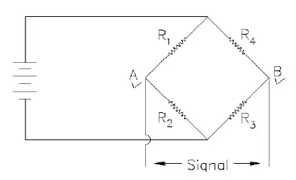
Figure 1 shows the primary electrical circuit used for strain gauge transducers – the Wheatstone Bridge.

In the bridge shown, assume that resistors R1, R2, R3, and R4 are strain gauges. If the resistance of all the strain gauges is exactly equal, the bridge is said to be “balanced” and no output voltage will appear at the signal leads. If, however, one of the strain gauges (say R1) happens to increase in value, the bridge is no longer balanced and a voltage proportional to the increase in resistance will appear across the signal leads (if R1 increases, voltage at point A will be lower than at point B. Likewise, if R1 decreases in value, the voltage at point A will be higher than at point B). With very little imagination, it is easy to extend this circuit by noting that the voltage at point B will be lower than that at point A if R1 and/or R3 decrease or if R4 and/or R2 increase. If you have digested this paragraph, you have successfully mastered most of the principles behind the Wheatstone Bridge.
Restating the previous paragraph, it can be said that the Wheatstone Bridge will develop a signal which is proportional to the increase in resistance in arms 1 and 3 and the decrease in resistance in arms 2 and 4.
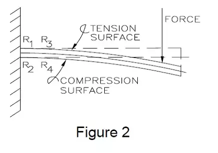
When a load is applied to a transducer, the strain gauges (R1, R2, R3, and R4) are applied to the structure in such a manner that causes gauges 1 and 3 to stretch (undergo tension) and, therefore, increase in resistance, while gauges 2 and 4 are compressed which causes them to decrease in resistance. These load-caused resistance changes all contribute to generating the same polarity signal at the output terminals (A and B) and, therefore, the load cell gives a signal which is proportional to the applied load. The easiest structure to visualize these tension and compression caused resistance changes is the simple cantilever beam as shown in Figure 2.
If, however, we subjected the transducer to an increase of temperature, all of the component parts to which the strain gauges were attached would increase in length causing all gauges resistances to increase equally. (In this instance, the signal developed by the increase in resistance in arms 1 and 3 would be exactly cancelled by the increase in resistance in arms 2 and 4 and the net bridge output would be zero).

Subscribe for Insights
Industry insights, trends, events and unmissable content straight to your inbox
Sign up to our newsletter to get insider access to stay up to date with all things custom strain gauge sensing
Therefore, in a Wheatstone Bridge, if we can make each arm change identically with temperature, we can eliminate the “temperature effect on zero” for the transducer. Even better, if we would somehow make the temperature caused changes in resistance of the strain gauges small or zero, the nulling effect of the Wheatstone Bridge would be even more effective.
In 1858, a gentleman by the name of Thompson (who later became known as Lord Kelvin), presented a paper before the Royal Society in London entitled “On the Electrodynamic Qualities of Metals,” where he reported that certain electrical conductors exhibited a “…change of electrical resistance with change in strain.” But he also stated that the resistance change was so small that delicate instruments were required to detect it.
At the same meeting, Sir Charles Wheatstone reported on work performed 23 years earlier by a Mr. S. Hunter Christie on an electrical bridge network which was capable of detecting very small resistance changes. The network eventually became associated with the reporter rather than the inventor and today the network is known as the “Wheatstone Bridge.”
Little use was made of Lord Kelvin’s discovery until 1937 when Professor Ruge of MIT unwound a wire wound resistor and used the wire to construct the first bondable strain gauge. At the same time, at Cal Tech University, a graduate lab assistant by the name of Ed Simmonds suggested doing the same thing to a researcher who not only published his research, but also credited Simmonds for the first bonded resistance strain gauge. Because of the simultaneity of discovery, a joint patent was issued to both inventors and the Simmonds Ruge (“SR-4”) strain gauge was born.
It turns out that the choice of wire used by both of the inventors was quite fortuitous. In order to produce stable wire wound resistors of reasonable size, resistor manufacturers had developed special alloys which had very high resistance (so that reasonable lengths of wire would produce the required resistance values), and possessed very small temperature coefficients of resistivity (which means that the resistance of the wire would not change with changes in temperature). The metallurgy of these alloys is relatively complex, and if the resistor industry hadn’t born the development cost, we still might not have the strain gauge. The choice of alloys was so good in fact that basically the same ones are being used in modern strain gauges 50 years later.
Even though the basic alloys used to make strain gauges haven’t changed, the strain gauge itself has. The major change was when the gauge started to be manufactured by using printed circuit techniques rather than simply winding a wire into a grid configuration. The use of foil permitted the gauge to be manufactured with great uniformity and also placed the gauge closer to the surface of the part to which it was bonded, which allowed it to operate at basically the same temperature as the part. It was then discovered that minor or subtle processing changes (primarily heat treating of the foil), could produce strain gauges with even more repeatable temperature coefficients of resistivity and even better, enabled the gauge manufacturer to produce slight negative coefficients.
To see what effect this has on a strain gauge, let’s assume that a gauge is mounted on a piece of steel which is heated 100°F. With this heating, the steel part expands .0006″ per inch of length. Since the strain gauge is attached to the part, it would be stretched and therefore increase in resistance. However, if the gauge alloy has been properly heat-treated, as the temperature goes up, the base resistance of the gauge goes down by exactly the same amount as it would have increased by the elongation of the part; thereby producing a strain gauge system that would not change in resistance with temperature.
This is the basic mechanism for producing self-temperature compensating strain gauges, and is the reason why gauges are specified by the temperature coefficient of expansion of the material to which the gauge is to be mounted.
Self-temperature compensating strain gauges, coupled with the temperature cancellation effects of the Wheatstone Bridge are quite effective in reducing temperature created “zero shifts” from transducers.
In commercially available transducers, it turns out that even these zero correction mechanisms are not quite\ good enough, and therefore additional temperature compensation elements are sometimes added to even further reduce the effects of temperature on the zero output of a transducer.
So far in this article I have discussed those factors which produce and prevent an erroneous signal being delivered from a transducer, as the temperature changes, with no applied load. These “zero balance” effects are quite easy to detect, since any indicated load reading from an unloaded transducer is obviously incorrect. If, however, the transducer changes its sensitivity, the only clue is to apply a known weight or force to the transducer and check its output. For installed scales, this checking procedure is inconvenient and in many cases, impossible to perform. Therefore, the temperature effects on span or sensitivity of a transducer is normally measured and corrected by the transducer manufacturer, and the end-user must trust that the manufacturer has performed the job correctly, since it is unlikely that the scale will ever be calibrated at two different temperatures unless it is suspected that the transducer is out of specification.
The reasons for the transducer’s temperature sensitivity with regard to span can easily be explained by examining a simple model of a transducer. A transducer can be considered as nothing more than a “spring-like” structure which deforms under load, and a sensor (such as a strain gauge) which produces a signal proportional to this deformation. The deflection of the transducer structure depends upon the magnitude of the applied load, the shape of the structure, and the properties of the material from which the structure is made. The material property which relates deflection to applied load is called the “Modulus of Elasticity” or the “Elastic Modulus”. If the Modulus of Elasticity of a material would remain constant, the deformation caused by an applied load would also remain constant.
Unfortunately, the Modulus of Elasticity for most materials changes slightly with temperature, the end result being that a typical transducer becomes “softer” as the temperature increases. If uncorrected, this “softening” effect would make the transducer more sensitive as the temperature increased. For most materials used in transducers, the magnitude of this effect is about 1.5% per 100°F.
A second effect which creates a change in sensitivity with temperature change, is associated with the strain gauges used to measure the deformation of the transducer structure. Strain gauges, depending upon which alloy is used in their construction, change their sensitivity from +.5%/100°F (Karma and Platinum/Tungsten). A transducer using Constantan strain gauges can be expected to increase its sensitivity by 2%/100°F due to the combined effect of elastic modulus decrease and the strain gauge sensitivity increase. In transducers, these two combined effects are commonly lumped together, and simply referred to as the modulus effect.
Since Karma and Platinum alloys decrease in sensitivity by approximately the same amount as the increase in sensitivity of the structure itself, some It should be emphasized that this correction network which is normally used by transducer manufacturers, will only work when the transducer is excited with constant VOLTAGE supplies. If constant CURRENT systems are used, the compensated system is completely nullified and a different compensation system must be used.
Manufacturers have produced sensors which possess self-modulus temperature compensation. In order for this self-compensation to occur, careful matching of the strain gauge to the structure is required, which implies some rather intensive testing to assure a consistent match. For this reason, this technique has been restricted to sensors in relatively high production where the initial evaluation costs can be amortized over the length of the production run.
Sensors constructed with Constantan strain gauges (even though they always require correction for their increase in sensitivity versus temperature), offer advantages in cost and stability that still make them desirable for most of the available transducers today. Also, if a constant voltage excitation system is used with the sensor, it turns out that a very simple addition to the Wheatstone bridge circuit will correct the sensor for modulus changes.
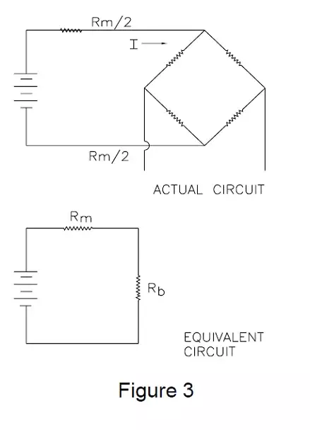
The output of a transducer is a function of the applied load and the excitation voltage. If we could somehow reduce the excitation voltage of a sensor at the same rate as it was increasing its sensitivity, the sensor would be effectively modulus compensated. The method used to accomplish this is simply to add a resistance in series with the Wheatstone bridge which increases with temperature.
The Wheatstone bridge, which is constructed with strain gauges that basically do not change resistance with temperature changes, can be considered simply as another single resistor in series with the temperature sensitive one. If a constant voltage is applied across this circuit, the current will decrease as the resistance increases in the temperature sensitive resistor. As this occurs, the effective voltage across the Wheatstone bridge decreases, since its resistance remains constant. In practice, this temperature sensitive resistor, which is referred to as the modulus resistor, is normally split into two resistors, with each resistor in series with each excitation lead going to the bridge circuit. (See Figure 3)

Speak to our experts
Provide us with your information and our team will contact you

Domenic El-Achkar
Domenic El-Achkar is Director of Engineering for HITEC Sensors. He started with the company in May of 2000, as a Co-Op student while earning his B.S. in Mechanical Engineering at UMass Lowell and later earning his MBA. Domenic has developed his engineering capabilities from applications support through design, test and measurement, management, and departmental leadership. Domenic combines broad technical knowledge with a commercial mindset and good communication skills to be a very effective customer-facing technical leader. He enjoys visiting customers, developing partnerships, innovative sensor designs, and helping customers solve problems.