A strain gauge with a resistance of 350 ohms and a gauge factor of 2 mounted to a structure subjected to strain level of 1000 micro-strain will change its resistance 0.7 ohms. While this resistance change can be sensed with one of the newer digital ohmmeters, if we wish to resolve 1/1000 of this applied load, we must sense the difference between 350.0000 and 350.0007 ohms.
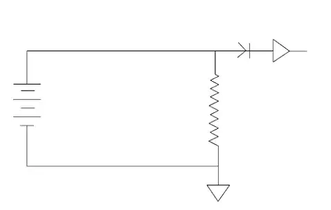
If the force we are trying to measure is of a dynamic nature, such as a part hitting a locating stop in a machine, the circuitry required can be as simple as exciting a single gauge with constant current and amplifying the AC component of the signal with an AC amplifier to produce a useable control signal. In this case, a capacitor is used to remove the large common mode voltage leaving only the signal to be amplified.

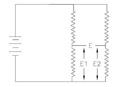
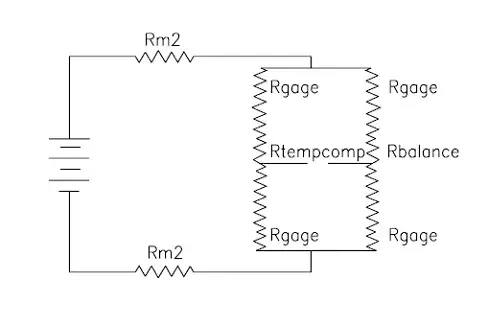
The Wheatstone bridge performs a similar function, and is useable for both static and dynamic force signals. The best visualization of the function of a Wheatstone bridge is to consider it as two simple voltage dividers connected to a common voltage source. If the resistors are of equal value in these dividers, the voltage present at the mid-points of each divider will be equal. A DC voltmeter connected between these two points will indicate zero voltage, even though both points are at a voltage potential of 1/2 the excitation voltage. A small change in any one of the resistors making up the dividers will cause and be indicated on the voltmeter. Since there exists only a strain produced signal at these points, a DC amplifier can be installed instead of a voltmeter and a high level signal produced, again independent of the large common mode voltage present at these two points.If a Wheatstone bridge circuit consists of 4 strain gauges of equal resistance, which are unstrained, the bridge is said to be “balanced” and no output voltage will be present at the bridge output terminals.
Subscribe for Insights
Industry insights, trends, events and unmissable content straight to your inbox
Sign up to our newsletter to get insider access to stay up to date with all things custom strain gauge sensing

As the structure to which the strain gauges relative change in the voltage dividers are attached is loaded, the gauge resistances either increase or decrease causing the bridge to become unbalanced and develop a proportionate signal. Depending upon the location of each gauge in the bridge, the resistance change will either add or subtract from the output signal. This inherent computation feature of the Wheatstone bridge is used for several purposes in the design of force sensors.
The general use of this feature is to eliminate resistance change effects which are not related to the desired strain related changes. Temperature, for example, will create an equal strain change in all gauges applied to the part. If all gauges are affected equally, the bridge will effectively cancel these temperature related changes. A beam gauged to sense bending will often have gauges mounted in “pairs” in which one gauge would measure the tension strain and the other the compression strain due to the bending moment at a particular beam section. By placing these two gauges in “adjacent” bridge “arms”, the signals, while opposite in sign, are additive relative to the bridge output. An end load applied to the beam will equally affect both gauges causing the bridge to cancel its effect on the apparent output of the bridge. This addition and subtraction of individual gauge signals is used to make force sensors which are sensitive to forces along defined axes.
It is important to note that in order for these extraneous signals to be cancelled, each gauge pair must have equal but opposite resistance changes. If one or more of these

Gauges is accidentally or intentionally “shunted” by an external passive resistance, not only does the gauge's base resistance change, but its effective sensitivity (Gauge Factor) also changes. This effect is often used to correct the “cross-talk” sensitivity of sensors to “fine tune” their sensitive force axis location in space. It is also unfortunately performed unknowingly by the users of sensors who apply external resistive networks directly across various bridge arms in an attempt to “balance” a sensor. Sometimes these parasitic shunt networks are found in commercially available “read out” instruments in the form of “T” balance networks and the user must be cautious in putting together a force measurement system or else he may find himself measuring something in addition to the parameter he is interested in.
Speak to our experts
Provide us with your information and our team will contact you

Domenic El-Achkar
Domenic El-Achkar is Director of Engineering for HITEC Sensors. He started with the company in May of 2000, as a Co-Op student while earning his B.S. in Mechanical Engineering at UMass Lowell and later earning his MBA. Domenic has developed his engineering capabilities from applications support through design, test and measurement, management, and departmental leadership. Domenic combines broad technical knowledge with a commercial mindset and good communication skills to be a very effective customer-facing technical leader. He enjoys visiting customers, developing partnerships, innovative sensor designs, and helping customers solve problems.